


反射マーカーとは何ですか?
3Dスキャンで反射マーカーが必要なのはなぜですか?
反射マーカー配置ガイダンス
ZG 3Dレーザースキャナーは、マーカーでスキャンするときに品質検査にどのように役立ちますか?
マーカーフリーソリューション
結論
1.反射マーカーとは何ですか?
反射マーカー\u003Ci>(also commonly known as positioning targets) are small stickers or magnets with a circular reflective area in the middle and a black outer ring.\u003C\/i> \u003Cb>(一般にポジショニングターゲットとも呼ばれます)は、中央に円形の反射領域があり、外側のリングが黒い小さなステッカーまたは磁石です。\u003C\/b> \u003Ci>Reflective markers are placed on the object or its surroundings before 3D scanning, the 3D scanner can easily detect these “high-contrast” targets during scanning and determine the scanner's location in space, this is the key to 3D scanner's portability and dynamic referencing.\u003C\/i>\u003Cb>反射マーカーは、3Dスキャンの前にオブジェクトまたはその周囲に配置されます。3Dスキャナーは、スキャン中にこれらの「高コントラスト」ターゲットを簡単に検出し、空間内のスキャナーの位置を特定できます。これは、3Dスキャナーの移植性と動的参照の鍵です。\u003C\/b>
\u003Ci>For ZG 3D laser scanners, the reflective markers are used for real-time tracking, allowing fast and accurate 3D scanning.\u003C\/i> \u003Cb>ZG 3Dレーザースキャナーの場合、反射マーカーはリアルタイムトラッキングに使用され、高速で正確な3Dスキャンを可能にします。\u003C\/b> \u003Ci>During scanning, when the ZG 3D scanner detects reflective markers on object surface individually, the ZGScan scanning software can recognize and analyze each marker in real time.\u003C\/i>\u003Cb>スキャン中に、ZG 3Dスキャナーがオブジェクト表面の反射マーカーを個別に検出すると、ZGScanスキャンソフトウェアは各マーカーをリアルタイムで認識して分析できます。\u003C\/b> \u003Ci>A data set with a minimum of 4 markers is used to position each scanning frame.\u003C\/i>\u003Cb>各スキャンフレームの配置には、最低4つのマーカーを含むデータセットが使用されます。\u003C\/b> \u003Ci>As the scanner moves around the object, the ZGScan scanning software records the exact location of each frame as they relate to each other and uses that information to align the data for 3D rendering in the software in real time.\u003C\/i>\u003Cb>スキャナーがオブジェクトの周りを移動すると、ZGScanスキャンソフトウェアは、各フレームが相互に関連している正確な位置を記録し、その情報を使用して、ソフトウェアで3Dレンダリング用のデータをリアルタイムで位置合わせします。\u003C\/b>
\u003Ci>After scanning, the reflective markers can be easily edited out in the data editing process;\u003C\/i>\u003Cb>スキャン後、反射マーカーはデータ編集プロセスで簡単に編集できます。\u003C\/b> \u003Ci>Besides that, the reflective markers can also be used as reference points to merge two scanning data.\u003C\/i>\u003Cb>さらに、反射マーカーは、2つのスキャンデータをマージするための参照ポイントとしても使用できます。\u003C\/b>
最も一般的に使用される2種類の反射マーカーは次のとおりです。
ステッカーマーカー:ステッカーマーカーは裏面に粘着性があり、オブジェクトに貼り付けることができ、手で簡単に剥がすことができます。
磁気マーカー:磁気マーカーは、鉄や鋼などの磁性体に簡単に取り付けることができ、再利用可能で、簡単に取り付けたり剥がしたりすることができます。
![]()
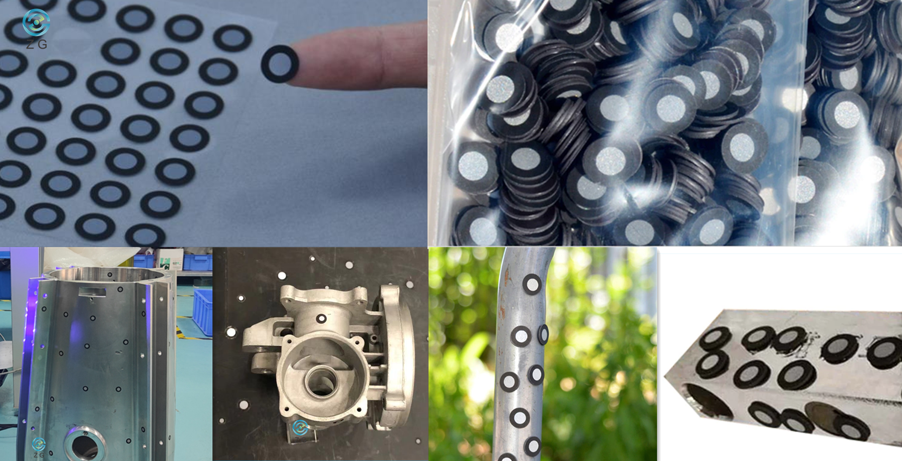 ステッカー反射マーカー磁気反射マーカー
2. 3Dスキャンで反射マーカーが必要なのはなぜですか?
3Dスキャナー\u003Ci>can be classified according to one of their main features: the positioning method.\u003C\/i>\u003Cb>主な特徴の1つである測位方法に従って分類できます。\u003C\/b> \u003Ci>Laser scanners project multiple laser lines on the object to be scanned, while structured-light (or white-light) scanners project light and shade patterns.\u003C\/i>\u003Cb>レーザースキャナーはスキャン対象のオブジェクトに複数のレーザーラインを投影しますが、構造化光(または白色光)スキャナーは明暗のパターンを投影します。\u003C\/b> \u003Ci>Both of them will take images and analyze the projection's specific deformation on the object to extract 3D data.\u003C\/i>\u003Cb>どちらも画像を撮影し、オブジェクトの投影の特定の変形を分析して3Dデータを抽出します。\u003C\/b>
\u003Ci>The scanning data is displayed in the form of point cloud or triangle mesh.\u003C\/i>\u003Cb>スキャンデータは、点群または三角形メッシュの形式で表示されます。\u003C\/b> \u003Ci>As the scanner moves around the object during scanning, different sets of scanning data are brought into a common coordinate, where data is merged into a complete model.\u003C\/i>\u003Cb>スキャナーがスキャン中にオブジェクトの周りを移動すると、スキャンデータのさまざまなセットが共通の座標になり、データが完全なモデルにマージされます。\u003C\/b> \u003Ci>This process is called alignment or registration, it can be done in real-time during the scanning process, or in the post-processing step.\u003C\/i>\u003Cb>このプロセスはアライメントまたは登録と呼ばれ、スキャンプロセス中にリアルタイムで実行することも、後処理ステップで実行することもできます。\u003C\/b>
反射マーカーを適用すると、3Dスキャンの2つの別々の問題が解決されます。正確なスキャンデータの位置合わせの難しさと、大きなオブジェクトでの高精度の達成の難しさです。
2.1正確なスキャンデータアライメントの難しさ
\u003Ci>As we know, the structured-light (or white-light) 3D scanners can generate complete 3D surface of an object without using a single reflective marker.\u003C\/i>\u003Cb>ご存知のように、構造化光(または白色光)3Dスキャナーは、単一の反射マーカーを使用せずに、オブジェクトの完全な3D表面を生成できます。\u003C\/b> \u003Ci>It has sophisticated algorithms which will align the scan images data based on geometric features of the object.\u003C\/i>\u003Cb>オブジェクトの幾何学的特徴に基づいてスキャン画像データを整列させる高度なアルゴリズムを備えています。\u003C\/b> \u003Ci>However, this kind of guesswork doesn't always lead to great results, and in many cases, especially for objects with large flat surfaces and no unique geometric feature, even the most sophisticated algorithm will fail.\u003C\/i>\u003Cb>ただし、この種の当て推量は必ずしも優れた結果をもたらすとは限りません。多くの場合、特に大きな平面があり、固有の幾何学的特徴がないオブジェクトの場合、最も高度なアルゴリズムでさえ失敗します。\u003C\/b>
\u003Ci>Imagine scanning a steel plate which is 8-meter long and 6-meter wide, there are no geometric features on the steel plate surface at all.\u003C\/i>\u003Cb>長さ8メートル、幅6メートルの鋼板をスキャンすると、鋼板の表面に幾何学的な特徴はまったくありません。\u003C\/b> \u003Ci>Placing reflective markers on the sheet plate surface can give the 3D scanner a “constant feature” to track, which enables the scanning software to register all different scanning frames for the 3D data sets, and align the 3D data sets to form complete 3D scanning data.\u003C\/i>\u003Cb>シートプレート表面に反射マーカーを配置すると、3Dスキャナーに追跡する「一定の機能」を与えることができます。これにより、スキャンソフトウェアは3Dデータセットのすべての異なるスキャンフレームを登録し、3Dデータセットを整列させて完全な3Dスキャンデータを形成できます。 。\u003C\/b> \u003Ci>If without reflective markers, the 3D scanner will lose its alignment and the software will not know how Frame1 is supposed to be aligned to Frame2, Frame2 to Frame3, and so on…\u003C\/i>\u003Cb>反射マーカーがない場合、3Dスキャナーはその位置合わせを失い、ソフトウェアはFrame1がFrame2に、Frame2がFrame3にどのように位置合わせされるかなどを認識しません…\u003C\/b>
2.2大きな物体で高精度を達成することの難しさ
\u003Ci>During scanning, when 3D scanner detects reflective markers on the object surface, it enables the scanner to determine its location in space based on relative position to the object, which is called self-positioning or dynamic referencing.\u003C\/i>\u003Cb>スキャン中に、3Dスキャナーがオブジェクト表面の反射マーカーを検出すると、スキャナーはオブジェクトに対する相対位置に基づいて空間内の位置を特定できます。これは、セルフポジショニングまたは動的参照と呼ばれます。\u003C\/b> \u003Ci>While as the scanner moves around the object during scanning, error can accumulate as the scanning volume grows, especially for large objects.\u003C\/i>\u003Cb>スキャナーがスキャン中にオブジェクトの周りを移動する間、特に大きなオブジェクトの場合、スキャンボリュームが大きくなるにつれてエラーが蓄積する可能性があります。\u003C\/b> \u003Ci>It is possible to minimize the accumulation of the error by using technologies such as photogrammetry and reflective markers.\u003C\/i>\u003Cb>写真測量や反射マーカーなどの技術を使用することにより、エラーの蓄積を最小限に抑えることができます。\u003C\/b>
\u003Ci>Before scanning, there is a process called pre-modeling to obtain a preliminary skeleton for the object to be scanned.\u003C\/i>\u003Cb>スキャンする前に、スキャンするオブジェクトの予備的なスケルトンを取得するためのプレモデリングと呼ばれるプロセスがあります。\u003C\/b> \u003Ci>Using a photogrammetry system to take photos of reflective markers on large object surface firstly, the photogrammetry system can triangulate the markers in the images to determine their location in a three-dimensional space.\u003C\/i>\u003Cb>写真測量システムを使用して、最初に大きな物体表面の反射マーカーの写真を撮ることで、写真測量システムは、画像内のマーカーを三角測量して、3次元空間での位置を決定できます。\u003C\/b> \u003Ci>When the markers data is imported into scanning software, it can help to constrain the scan data to generate exceptionally accurate and repeatable 3D data for large objects very quickly.\u003C\/i>\u003Cb>マーカーデータをスキャンソフトウェアにインポートすると、スキャンデータを制限して、大きなオブジェクトに対して非常に正確で再現性のある3Dデータを非常に迅速に生成できます。\u003C\/b>
よろしくお願いしますPhotoShotLite写真測量システムと反射マーカーが役立ちますZG3DスキャナーRigelScanPlus正確に実施する8m x 6mx5mおよび5mx 3mx2.5mの大型機器サブアセンブリの3D検査.
3.反射マーカー配置ガイダンス
マーカーの配置については、オペレーターは以下の点に注意する必要があります。
3.1オブジェクトにマーカーを配置する
\u003Ci>The reflective markers should cover the whole object surface, try to place the reflective markers on the flat area.\u003C\/i>\u003Cb>反射マーカーはオブジェクトの表面全体を覆う必要があります。反射マーカーを平らな領域に配置してみてください。\u003C\/b> \u003Ci>If the condition is restricted, place the markers on the less curved area as much as possible.\u003C\/i>\u003Cb>条件が制限されている場合は、できるだけ湾曲の少ない領域にマーカーを配置します。\u003C\/b> \u003Ci>If the markers deform at a large degree, the scanning accuracy will be influenced.\u003C\/i>\u003Cb>マーカーが大きく変形すると、スキャン精度に影響します。\u003C\/b>
\u003Ci>For ZG 3D scanners, at least 4 reflective markers have to be seen in every frame to perform normal 3D scanning.\u003C\/i> \u003Cb>ZG 3Dスキャナーの場合、通常の3Dスキャンを実行するには、すべてのフレームで少なくとも4つの反射マーカーを確認する必要があります。\u003C\/b> \u003Ci>For standard and wide-range scanning, the operator can apply Φ6mm reflective markers and place the markers at the distance of 60mm-100mm between each marker;\u003C\/i>\u003Cb>標準および広範囲のスキャンの場合、オペレーターはΦ6mm反射マーカーを適用し、各マーカー間の60mm〜100mmの距離にマーカーを配置できます。\u003C\/b> \u003Ci>For specific areas needing ultra-fine scanning, apply Φ3mm reflective markers and place the markers at the distance of 20mm-50mm.\u003C\/i>\u003Cb>超微細スキャンが必要な特定の領域には、Φ3mm反射マーカーを適用し、マーカーを20mm〜50mmの距離に配置します。\u003C\/b>
3.2オブジェクトの周囲にマーカーを配置する
\u003Ci>When the part is too small or the reflective markers can't be placed properly on the object surface, markers can be placed around the object's surroundings.\u003C\/i>\u003Cb>パーツが小さすぎる場合、または反射マーカーをオブジェクトの表面に適切に配置できない場合は、マーカーをオブジェクトの周囲に配置できます。\u003C\/b> \u003Ci>For this circumstance, please make sure the relative position of reflective markers and object remains the same during scanning.\u003C\/i>\u003Cb>このような状況では、スキャン中に反射マーカーとオブジェクトの相対位置が同じであることを確認してください。\u003C\/b>
![]()

3.3反射マーカーの配置に関する注意事項
3.3.1曲率の高い表面にマーカーを配置しないでください。
3.3.2オブジェクトのエッジ\/詳細の近く(<4mm)にマーカーを配置しないでください。
3.3.3マーカーを一列に並べたり、等距離に配置したりしないでください(3Dスキャナーでは正確な計算を実行できません)。
3.3.4マーカーを三角形や正方形などの通常の形で配置しないでください。
3.3.5損傷、不完全、脂っこい、または汚れたマーカーは使用しないでください。
間違った例は次のとおりです。

3.4もっと知っておくべきこと
\u003Ci>3.4.1 The 3D scanner might sometimes doesn't see a reflective marker when scanning from a large angle.\u003C\/i> \u003Cb>3.4.1 3Dスキャナーは、大きな角度からスキャンするときに反射マーカーを認識しない場合があります。\u003C\/b> \u003Ci>This means that when scanning around a bending area (like from the front bumper of the car to the back door), try to place more reflective markers in the field of view.\u003C\/i>\u003Cb>これは、曲がりくねった領域(車のフロントバンパーからバックドアまでなど)をスキャンするときは、視野内により多くの反射マーカーを配置するようにすることを意味します。\u003C\/b>
\u003Ci>3.4.2 The ZGScan and HyperScan scanning software can display how many markers the 3D scanner is seeing in real-time.\u003C\/i> \u003Cb>3.4.2 ZGScanおよびHyperScanスキャンソフトウェアは、3Dスキャナーが認識しているマーカーの数をリアルタイムで表示できます。\u003C\/b> \u003Ci>If you are not sure about whether you've placed enough markers on the object, turn on the scanner and click \\"Scan Markers\\" in the scanning software, you will see how many markers the scanner sees in each frame and if more markers are needed.\u003C\/i>\u003Cb>オブジェクトに十分なマーカーを配置したかどうかわからない場合は、スキャナーの電源を入れ、スキャンソフトウェアの[スキャンマーカー]をクリックすると、スキャナーが各フレームに表示するマーカーの数と、さらにマーカーが表示されるかどうかがわかります。必要です。\u003C\/b>
4. ZG 3Dレーザースキャナーは、マーカーでスキャンするときに品質検査にどのように役立ちますか?
射出成形金型は、当初の設計どおりの寸法と精度で性能を維持できるように、重要な改修のために定期的に厳密に保守する必要があります。
\u003Ci>With multi-mode, versatile metrology-grade 3D scanner -- AtlaScan, we can scan the markers on the mold first to get an overall shape of the entire mold and the markers spatial data, which we can import into the scanning software and scan the surface of the mold.\u003C\/i>\u003Cb>マルチモードで用途の広い計測グレードの3DスキャナーであるAtlaScanを使用すると、最初に金型上のマーカーをスキャンして、金型全体の全体的な形状とマーカーの空間データを取得できます。これらのデータをスキャンソフトウェアにインポートして、スキャンすることができます。金型の表面。\u003C\/b> \u003Ci>During the surface scanning process, the scan data will be automatically aligned to the imported markers data, the scanning data is tightly constrained and extremely accurate.\u003C\/i>\u003Cb>表面スキャンプロセス中、スキャンデータはインポートされたマーカーデータに自動的に位置合わせされ、スキャンデータは厳しく制限され、非常に正確になります。\u003C\/b> \u003Ci>Then the 3D scanning data is compared with original CAD model to generate 3D color map and inspection report, the engineers can know if the mold needs refurbishing or not clearly.\u003C\/i>\u003Cb>次に、3Dスキャンデータを元のCADモデルと比較して、3Dカラーマップと検査レポートを生成します。エンジニアは、金型の改修が必要かどうかを明確に知ることができます。\u003C\/b>
![]()

AtlaScan-金型検査用の反射マーカーを使用したスキャン
具体的なプロセスは以下のとおりです。
1.金型表面に十分な反射マーカーを適切に配置します。
2. AtlaScanを電源に接続し、スキャナーを20分間ウォームアップします。
3. ZGScanソフトウェアで[スキャンマーカー]をクリックし、金型表面のすべてのマーカーをキャプチャして、マーカーデータをエクスポートします。
4. [マーカーのインポート]をクリックして、マーカーデータをZGScanソフトウェアにインポートします。
5. [表面のスキャン]をクリックして、金型表面のスキャンを開始します。
6.スキャンデータを処理し、.stlの形式で保存します。
7.スキャンデータをサードパーティのソフトウェアにインポートして、3Dカラーマップと検査レポートを生成します。
詳細についてはZGプロフェッショナル計測グレード3DレーザースキャナーAtlaScan、 チェックしてくださいZGプロフェッショナル計測グレード3DレーザースキャナーAtlaScan.
5.マーカーフリーソリューション
\u003Ci>During daily communications with customers, we have received many different iterations of the same question over and over.\u003C\/i>\u003Cb>お客様との日々のコミュニケーションの中で、同じ質問を何度も何度も繰り返し受けてきました。\u003C\/b> \u003Ci>Something along the lines of: “Do we have to place markers on the part?”\u003C\/i> \u003Cb>「パーツにマーカーを配置する必要がありますか?」\u003C\/b> \u003Ci>or “Is there any way can save us the time of placing markers on the object surface?”.\u003C\/i>\u003Cb>または「オブジェクトの表面にマーカーを配置する時間を節約できる方法はありますか?」\u003C\/b> \u003Ci>Reflective markers benefit fast and accurate 3D scanning, while sometimes the markers placement does increase the setup time and limit the size of objects that can be scanned efficiently.\u003C\/i>\u003Cb>反射マーカーは高速で正確な3Dスキャンに役立ちますが、マーカーの配置によってセットアップ時間が長くなり、効率的にスキャンできるオブジェクトのサイズが制限される場合があります。\u003C\/b>
ZGテクノロジーは高品質の製品を継続的に改善しているため、以下の2つのマーカーフリースキャンシステムは、ユーザーがオブジェクト表面にマーカーを配置する時間を節約し、スキャン効率を劇的に向上させるのに役立ちます。
5.1 HyperScan Optical Tracking3Dレーザースキャナー![]()
![]()
スマートオプティカルトラッキング3Dスキャナー、HyperScan\u003Ci>, adopts blue laser technology with multiple working modes.\u003C\/i> \u003Cb>、複数の動作モードを備えた青色レーザー技術を採用しています。\u003C\/b> \u003Ci>The hardware of HyperScan is composed of an optical tracker and a handheld 3D laser scanner with a rigid structure marker frame.\u003C\/i> \u003Cb>HyperScanのハードウェアは、光学トラッカーと、剛性構造のマーカーフレームを備えたハンドヘルド3Dレーザースキャナーで構成されています。\u003C\/b> \u003Ci>During the scanning process, the optical tracker will track the markers on the scanner and establish the scanner's position in the space.\u003C\/i>\u003Cb>スキャンプロセス中、光学トラッカーはスキャナー上のマーカーを追跡し、空間内でのスキャナーの位置を確立します。\u003C\/b> \u003Ci>Thus there is no need to place positioning markers on the measured workpiece, which not only improves the convenience of operating the handheld scanner but also truly realizes instant scanning at the scanning site.\u003C\/i>\u003Cb>したがって、測定されたワークピースにポジショニングマーカーを配置する必要がないため、ハンドヘルドスキャナーの操作の利便性が向上するだけでなく、スキャンサイトでのインスタントスキャンが真に実現されます。\u003C\/b>
5.2MarvelScanトラッカー-無料およびマーカーフリーの3Dレーザースキャナー
![]()
MarvelScan\u003Ci>, the first Tracker-free and marker-free portable 3D laser scanner in the world, is a breakthrough product to change the working method of a portable 3D laser scanner with faster scanning efficiency.\u003C\/i> \u003Cb>、世界初のトラッカーフリーおよびマーカーフリーのポータブル3Dレーザースキャナーは、より高速なスキャン効率でポータブル3Dレーザースキャナーの作業方法を変える画期的な製品です。\u003C\/b> \u003Ci>Thanks to the unique Inside-Out monocular positioning technology, during the whole scanning procedure, the operator does not need to place sticker markers at all.\u003C\/i>\u003Cb>独自のInside-Out単眼ポジショニング技術のおかげで、スキャン手順全体を通して、オペレーターはステッカーマーカーをまったく配置する必要がありません。\u003C\/b> \u003Ci>Compared to other optical tracking scanning system, MarvelScan does not require a rigid structure with markers around the scanner or an optical tracker at all, which improves portability and simplify the calibration procedure dramatically.\u003C\/i>\u003Cb>他の光学追跡スキャンシステムと比較して、MarvelScanは、スキャナーまたは光学トラッカーの周囲にマーカーを備えた堅固な構造をまったく必要としないため、携帯性が向上し、キャリブレーション手順が大幅に簡素化されます。\u003C\/b>
6.結論
\u003Ci>With the help of reflective markers, 3D scanners are more and more used to get complete or partial 3D measurements of any physical object.\u003C\/i>\u003Cb>反射マーカーの助けを借りて、3Dスキャナーは、あらゆる物理的オブジェクトの完全または部分的な3D測定を取得するためにますます使用されています。\u003C\/b> \u003Ci>3D scanners can generate millions of points per second, the measurement and inspection efficiency are much higher when compared to traditional “point-by-point” measurement devices.\u003C\/i> \u003Cb>3Dスキャナーは毎秒数百万のポイントを生成でき、従来の「ポイントバイポイント」測定デバイスと比較すると、測定と検査の効率がはるかに高くなります。\u003C\/b> \u003Ci>Meanwhile, ZG Technology also offers Marker-Free solutions that the operators don't need to place markers on object surface at all.\u003C\/i>\u003Cb>一方、ZGテクノロジーは、オペレーターがオブジェクトの表面にマーカーを配置する必要がまったくないマーカーフリーソリューションも提供します。\u003C\/b> \u003Ci>If you have any other questions about reflective markers or ZG 3D scanning solutions, please feel free to contact ZG Technology for further discussions.\u003C\/i>\u003Cb>反射マーカーまたはZG3Dスキャンソリューションについて他に質問がある場合は、ZGテクノロジーに連絡して詳細を確認してください。\u003C\/b>
